カテゴリ:

今回はコンフィギュレーションの変更通知を設定します。この設定を行うことにより設定がいつ行われたかの詳細を保存することが可能です。

R1(config)#archive
R1(config-archive)#log config
R1(config-archive-log-cfg)#logging enable

設定後、設定を確認します。初期値でhidekeysが有効になっていることが分かります。

R1(config-archive-log-cfg)#do sh run | b archive
archive
log config
  logging enable
  hidekeys
!
〜略〜

ここでs1/0をno shutして確認します。

R1(config-archive-log-cfg)#int s1/0
R1(config-if)#no sh

show archiveコマンドを利用することで、設定の変更が確認できます。

R1#show archive log config all
idx   sess           user@line      Logged command
    1     1        console@console  |  logging enable
    2     1        console@console  |do sh run | b archive
    3     1        console@console  | interface Serial1/0
    4     1        console@console  | no shutdown

telnetでR1にユーザciscoでログインし、s1/0をshutした場合の出力です。

   15     0          cisco@vty0     |!exec: enable
   16     6          cisco@vty0     |interface Serial1/0
   17     6          cisco@vty0     | shutdown

ここまでの表示では日時は表示されません。出力をログに送ることで日時も表示されるようになります。

R1(config)#archive
R1(config-archive)#log config
R1(config-archive-log-cfg)#notify syslog

May 16 06:08:04.651: %PARSER-5-CFGLOG_LOGGEDCMD: User:console  logged command:notify syslog
May 16 06:08:36.403: %PARSER-5-CFGLOG_LOGGEDCMD: User:console  logged command:interface Serial1/0
May 16 06:08:38.483: %PARSER-5-CFGLOG_LOGGEDCMD: User:console  logged command:no shutdown

初期値で設定されているhidekeysはパスワード情報を隠して表示します。

R1(config)#username apple secret apple

May 16 07:10:25.655: %PARSER-5-CFGLOG_LOGGEDCMD: User:cisco  logged command:username apple secret *****

hidekeysをあえて無効にすると、パスワードがそのまま表示されることが分かります。

R1(config-archive-log-cfg)#no hidekeys
R1(config)#username lemon secret lemon

May 16 07:11:21.391: %PARSER-5-CFGLOG_LOGGEDCMD: User:console  logged command:username lemon secret lemon

loggingコマンドでログサーバを指定することで、外部に履歴を保存することも可能です。Linux(Red Hat系)に送った場合、初期値では/var/log/messagesに保存されることが分かります。

R1(config)#logging 192.168.0.180
# tail -f /var/log/messages
May 16 21:59:36 192.168.0.100 61: May 16 07:10:59.175: %PARSER-5-CFGLOG_LOGGEDCMD: User:cisco  logged command:archive
May 16 21:59:41 192.168.0.100 62: May 16 07:11:04.711: %PARSER-5-CFGLOG_LOGGEDCMD: User:cisco  logged command:log config
May 16 21:59:44 192.168.0.100 63: May 16 07:11:06.899: %PARSER-5-CFGLOG_LOGGEDCMD: User:cisco  logged command:no hidekeys
May 16 21:59:58 192.168.0.100 64: May 16 07:11:21.391: %PARSER-5-CFGLOG_LOGGEDCMD: User:console  logged command:username lemon secret lemon

カテゴリ:

今回はIOSでのログをLinuxで記録する設定を行います。R1はF0/1(192.168.0.100)でLANに接続されています。LinuxサーバのIPアドレスは192.168.0.180です。

R1#show ip interface brief
Interface                  IP-Address      OK? Method Status                Protocol
FastEthernet0/0            12.12.12.1      YES manual up                    up
FastEthernet0/1            192.168.0.100   YES manual up                    up
Loopback0                  17.17.1.1       YES NVRAM  up                    up

R1#ping 192.168.0.180

Type escape sequence to abort.
Sending 5, 100-byte ICMP Echos to 192.168.0.180, timeout is 2 seconds:
!!!!!
Success rate is 100 percent (5/5), round-trip min/avg/max = 1/4/8 ms

Linuxで外部のログを受け取るにはsyslogd起動時に-rオプションが必要です。/etc/sysconfig/syslogに設定を追加して、syslogdを再起動します。

# grep 'SYSLOGD_OPTIONS' /etc/sysconfig/syslog
SYSLOGD_OPTIONS="-m 0 -r"
# /etc/rc.d/init.d/syslog restart

まずIOSからログを送信するにはloggingコマンドでsyslogサーバを指定します。

R1(config)#logging 192.168.0.180 (logging host 192.168.0.180 も可)

設定の確認にはshow loggingを利用します。初期値では一般的に利用される、UPD ポート514が指定されることが分かります。

R1(config)#do sh loggi | i Logging to
        Logging to 192.168.0.180  (udp port 514,  audit disabled,

ここでF0/0をshutし、Linuxにログが届くかを確認します。

R1(config)#int f0/0
R1(config-if)#sh


# tail -f /var/log/messages
May 10 20:08:01 192.168.0.100 56: May 10 07:37:20.291: %DUAL-5-NBRCHANGE: IP-EIGRP(0) 100: Neighbor 12.12.12.2 (FastEthernet0/0) is down: interface down
May 10 20:08:03 192.168.0.100 57: May 10 07:37:22.259: %LINK-5-CHANGED: Interface FastEthernet0/0, changed state to administratively down
May 10 20:08:03 192.168.0.100 58: May 10 07:37:23.259: %LINEPROTO-5-UPDOWN: Line protocol on Interface FastEthernet0/0, changed state to down

ログが保存されていることが分かりました。この設定を全てのルータで行えば、ログが集中管理できることが分かります。

現在のログを見ると、送信元はF0/1(192.168.0.100)になっています。変更するにはlogging source-interfaceコマンドを利用します。ここではLo0を指定してみました。

R1(config)#logging source-interface loopback 0
R1(config)#int f0/0
R1(config-if)#no sh

送信元が変更されたことが分かります。

May 10 20:11:43 17.17.1.1 59: May 10 07:40:57.567: %LINK-3-UPDOWN: Interface FastEthernet0/0, changed state to up

/etc/hostsにホスト名を登録するとより判別しやすくなります。

# grep r1 /etc/hosts
17.17.1.1       r1.example.com r1

May 10 20:14:01 r1.example.com 63: May 10 07:43:20.455: %DUAL-5-NBRCHANGE: IP-EIGRP(0) 100: Neighbor 12.12.12.2 (FastEthernet0/0) is down: interface down

IOSからのログを個別に保存したい場合はファシリティを利用します。ここではlocal5を指定しました。

R1(config)#logging facility local5

Linuxでファシリティlocal5を独立したファイル/var/log/iosに保存する場合の設定例です。/var/log/messagesにlocal5.noneを追加することでログが二重に保管されることを防いでいます。

# grep 'local5' /etc/syslog.conf
*.info;mail.none;authpriv.none;cron.none;local5.none            /var/log/messages
local5.*                                                /var/log/ios

これ以降、ログは専用のファイル(/var/log/ios)にのみ保存されることが分かります。

# tail -f /var/log/ios /var/log/messages

==> /var/log/ios <==
May 10 20:28:30 r1.example.com 81: May 10 07:57:49.123: %DUAL-5-NBRCHANGE: IP-EIGRP(0) 100: Neighbor 12.12.12.2 (FastEthernet0/0) is down: interface down

カテゴリ:

今回はIOSでのFTPの利用を確認します。R1のF0/1のIPアドレスは192.168.0.100で、FTPサーバは192.168.0.180です。

R1#show ip interface brief
Interface                  IP-Address      OK? Method Status                Protocol
FastEthernet0/0            12.12.12.1      YES manual up                    up
FastEthernet0/1            192.168.0.100   YES manual up                    up

まず何も設定していない状態で利用してみます。下記はR1のstartup-configをFTPサーバにコピーする例ですが、失敗しています。

R1#copy startup-config ftp:
Address or name of remote host []? 192.168.0.180
Destination filename [r1-confg]?
Writing r1-confg
%Error opening ftp://192.168.0.180/r1-confg (Permission denied)

FTPサーバでのログ(/var/log/vsftpd.log)はこのようになりました。ユーザ名がftp、パスワードはrouter@cisco.coとなっています。ユーザ名がftpまたはanonymousである場合はアノニマス(匿名)FTPといい、誰もがログイン可能な設定です。この時、パスワードはチェックされないので何を入れても大丈夫です。ただしアノニマスFTPではセキュリティ上、ダウンロードのみが許可されアップロードは許可されないのが一般的な設定です。この理由より、コピーは失敗しました。

Wed May  4 16:15:14 2011 [pid 18496] CONNECT: Client "192.168.0.100"
Wed May  4 16:15:14 2011 [pid 18495] [ftp] OK LOGIN: Client "192.168.0.100", anon password "router@cisco.co"

今度は逆にFTPサーバ上のファイル(orange)をflashにダウンロードしてみます。問題なく利用出来ることが分かります。

R1#copy ftp: flash:
Address or name of remote host []?
192.168.0.180
Source filename []? orange
Destination filename [orange]?
Accessing ftp://192.168.0.180/orange...
Erase flash: before copying? [confirm]
Erasing the flash filesystem will remove all files! Continue? [confirm]
Erasing device... eeeeeeeeeeeeeeeeeeeeeeeeeeeeeeeeeeeeeeeeeeeeeeeeeeeeeeeeeeeeeee ...erased
Erase of flash: complete
Loading orange
[OK - 12/4096 bytes]

Verifying checksum...  OK (0x3E66)
12 bytes copied in 0.144 secs (83 bytes/sec)

R1#more flash:orange
Hello! IOS.

ユーザ名を指定してFTPを利用するには予めユーザ名とパスワードを設定します。FTPサーバにはユーザ名cisco、パスワードciscoがすでに登録されています。

R1(config)#ip ftp username cisco
R1(config)#ip ftp password cisco

ここで最初に試してみたR1のstartup-configをFTPサーバに再度コピーしてみます。

R1#copy running-config ftp:
Address or name of remote host []? 192.168.0.180
Destination filename [r1-confg]?
Writing r1-confg !
1347 bytes copied in 4.276 secs (315 bytes/sec)

実行されました。FTPサーバのログをみるとユーザciscoでログインしていることが分かります。

Wed May  4 16:33:00 2011 [pid 18573] CONNECT: Client "192.168.0.100"
Wed May  4 16:33:00 2011 [pid 18572] [cisco] OK LOGIN: Client "192.168.0.100"
Wed May  4 16:33:00 2011 [pid 18574] [cisco] OK UPLOAD: Client "192.168.0.100", "/home/cisco/r1-confg", 1347 bytes, 68.91Kbyte/sec

念の為にFTPサーバにあるファイルを開いてみます。

# head -5 /home/cisco/r1-confg

!
! Last configuration change at 15:14:03 JST Wed May 4 2011
!
version 12.4

このようにFTPサーバが設定されていれば、コンフィグファイルのバックアップなどを簡単に取ることが可能です。

カテゴリ:

今回はSCPを利用したファイルの転送を設定します。以前のIOSはftp-serverコマンドを利用してFTPサーバとして稼動させることが出来ましたが、現在は通常利用出来ません。代わりにより安全なSCPを使います。SCPはSSHの機能の一つで、暗号化した状態でファイルを転送しますのでFTPより安全です。

SCPを利用するには、SSHが必要です。まず、SSHを有効にします。

R1(config)#ip domain-name example.com
R1(config)#crypto key generate rsa modulus 1024

F0/0はR2(12.12.12.2)に接続されており、F0/1はLANでLinuxサーバと接続されています。

R1(config)#do sh ip int b
Interface                  IP-Address      OK? Method Status                Protocol
FastEthernet0/0            12.12.12.1      YES manual up                    up
FastEthernet0/1            192.168.0.100   YES manual up                    up

まず認証のためにAAAを有効にします。

R1(config)#aaa new-model

AAAでauthentication loingとauthorization execを有効します。今回はローカル認証を利用します。

R1(config)#aaa authentication login default local
R1(config)#aaa authorization exec default local

認証に使うユーザを作成します。ユーザ名とパスワード共、ciscoにしました。privilegeの設定に注意が必要です。レベルによってファイルの保存がエラーになります。

R1(config)#username cisco privilege 15 secret cisco

最後にip scp server enableでSCPを有効にします。SSHを有効にしただけではSCPは利用できません。

R1(config)# ip scp server enable

接続の確認のためにデバグを有効します。

R1#debug ip scp
Incoming SCP debugging is on

まずLinuxにあるファイル(scp-test.txt)をR1に転送します。ここではルータのflashに保存を実行しています。ファイル名(from_linux)まで指定します。

$ cat scp-test.txt
File from Linux to IOS.
$ scp scp-test.txt cisco@192.168.0.100:flash:from_linux
The authenticity of host '192.168.0.100 (192.168.0.100)' can't be established.
RSA key fingerprint is 1d:a4:f5:d8:f8:88:6c:03:41:2c:b7:e2:d7:da:d1:51.
Are you sure you want to continue connecting (yes/no)? yes
Warning: Permanently added '192.168.0.100' (RSA) to the list of known hosts.
Password: ← パスワードを入力
scp-test.txt                                  100%   24     0.0KB/s   00:00

R1のログを確認し、届いたファイルをmoreコマンドで表示しています。

R1#
Apr 25 07:53:26.823: SCP: [22 -> 192.168.0.180:34063] send <OK>
Apr 25 07:53:26.843: SCP: [22 <- 192.168.0.180:34063] recv C0644 24 scp-test.txt
Apr 25 07:53:26.855: SCP: [22 -> 192.168.0.180:34063] send <OK>
Apr 25 07:53:26.875: SCP: [22 <- 192.168.0.180:34063] recv 24 bytes
Apr 25 07:53:27.071: SCP: [22 <- 192.168.0.180:34063] recv <OK>
Apr 25 07:53:27.075: SCP: [22 -> 192.168.0.180:34063] send <OK>
Apr 25 07:53:27.079: SCP: [22 <- 192.168.0.180:34063] recv <EOF>
R1#
R1#dir flash:
Directory of flash:/

   12  -rw-          24  Apr 25 2011 16:53:27 +09:00  from_linux

16777212 bytes total (16499660 bytes free)
R1#more flash:from_linux
File from Linux to IOS.

IOSからSCPを利用するにはcopyコマンドを利用します。下記はrunning-configをコピーする例です。

R2#copy running-config scp://cisco@12.12.12.1/
Address or name of remote host [12.12.12.1]?
Destination username [cisco]?
Destination filename [r2-confg]?
Writing r2-confg
Password:
← パスワードを入力
!
1289 bytes copied in 14.320 secs (90 bytes/sec)

転送されていることが分かります。

R1#dir flash:
Directory of flash:/
〜略〜
   15  -rw-        1289  Apr 25 2011 17:00:09 +09:00  r2-confg
〜略〜
R1#more flash:r2-confg
!
! Last configuration change at 15:13:53 JST Mon Apr 25 2011
!
version 12.4
〜略〜

ANA機体工場見学の写真

カテゴリ:

ANAの機体工場見学に行きました。間近で見る飛行機は本当に大きくてビックリします。いずれJALの方も行ってみたい。

Boeing 777-300

__.JPG

Boeing 747-400

Boeing 767-300

Boeing 767-300

Boeing 767-300

カテゴリ:

現在ではCCNAでもルータのアクセスに関してSSHの問題が出るようです。Linuxなどではかなり前からtelnetは標準で無効であり、当然といえば当然ですが…。

今回はSSHの基本的な利用を確認します。初期値ではSSHは無効になっています。

R1#sh ip ssh
SSH Disabled - version 1.99
%Please create RSA keys (of atleast 768 bits size) to enable SSH v2.
Authentication timeout: 120 secs; Authentication retries: 3

SSHを利用するにはRSAキーを作成します。

R1(config)#crypto key generate rsa modulus 1024
% Please define a domain-name first.

ただ上記の結果から分かるとおり、あらかじめドメイン名の指定が必須です。

R1(config)#ip domain-name example.com
R1(config)#crypto key generate rsa modulus 1024
The name for the keys will be: R1.example.com

% The key modulus size is 1024 bits
% Generating 1024 bit RSA keys, keys will be non-exportable...[OK]

この時点でSSHで接続が可能となります。

R1(config)#
Apr 20 05:52:11.391: %SSH-5-ENABLED: SSH 1.99 has been enabled

R1(config)#do sh ip ssh
SSH Enabled - version 1.99
Authentication timeout: 120 secs; Authentication retries: 3

接続を行うユーザを作成します。

R1(config)#username cisco secret cisco

そしてローカル認証を有効にします。

R1(config)#line vty 0 15
R1(config-line)#login local
R1#debug ip ssh client
SSH Client debugging is on

では隣接するR2(12.12.12.2)よりR1(12.12.12.1)にSSHでログインします。R2では特に設定は必要ありません。またWindowsなどからでももちろん利用できます。

IOSでsshコマンドを利用するには-lオプションでユーザ名を指定します。

R2#ssh -l cisco 12.12.12.1

Password: ← パスワードを入力

R1>

この時、R1では下記のようなログが表示されます。

R1#
Apr 20 06:26:07.135: SSH0: sent protocol version id SSH-1.99-Cisco-1.25
Apr 20 06:26:07.147: SSH0: protocol version id is - SSH-1.99-Cisco-1.25

このまま利用するにはあまりセキュリティ的に望ましくないので、まずアクセスリストを設定します。この設定により12.12.12.0/24からの接続のみが許可されます。

R1(config)#access-list 1 per 12.12.12.0 0.0.0.255
R1(config)#line
R1(config)#line vty 0 15
R1(config-line)#access-class 1 in
R1(config-line)#do sh ip acce 1
Standard IP access list 1
    10 permit 12.12.12.0, wildcard bits 0.0.0.255 (2 matches)

この時点ではTELNETが有効です。せっかくSSHを有効にしたのに、このままでは意味がありません。SSHのみでの接続とするにはtransport inputコマンドを利用します。

R1(config)#line vty 0 15
R1(config-line)#transport input ssh

この時点でR2からのTELNETが利用できくなりました。

R2#telnet 12.12.12.1
Trying 12.12.12.1 ...
% Connection refused by remote host

初期値の設定ではSSHのバージョン1とバージョン2の両方が有効ですが、古いバージョン1をあえて利用する必要はありません。無効にします。sshコマンドで-vオプションを利用するとバージョンを指定できます。

R2#ssh -l cisco -v 1 12.12.12.1

下記はバージョン1で接続されたときのR1のログです。

Apr 20 06:35:27.827: SSH0: sent protocol version id SSH-1.99-Cisco-1.25
Apr 20 06:35:27.831: SSH0: protocol version id is - SSH-1.5-Cisco-1.25

R1でバージョン2のみを許可するように変更します。

R1(config)#do sh ip ssh
SSH Enabled - version 1.99
Authentication timeout: 120 secs; Authentication retries: 3
R1(config)#ip ssh version ?
  <1-2>  Protocol version

R1(config)#ip ssh version 2
R1(config)#do sh ip ssh
SSH Enabled - version 2.0
Authentication timeout: 120 secs; Authentication retries: 3

するとR2からバージョン1での接続が不可能になり、かなり安全な設定となりました。

R2#ssh -l cisco -v 1 12.12.12.1

[Connection to 12.12.12.1 aborted: error status 0]

R1(config)#
Apr 20 06:38:33.671: SSH0: Session terminated normally
Apr 20 06:38:35.567: SSH0: sent protocol version id SSH-2.0-Cisco-1.25
Apr 20 06:38:35.579: SSH0: receive failure - status 0x07
Apr 20 06:38:35.683: SSH0: Session disconnected - error 0x07

SSHの設定をする時にはip ssh logging eventsを有効にすると便利です。

R1(config)# ip ssh logging events
R1(config)#
Apr 20 06:46:32.455: SSH0: sent protocol version id SSH-2.0-Cisco-1.25
Apr 20 06:46:32.463: SSH0: protocol version id is - SSH-1.99-Cisco-1.25
Apr 20 06:46:32.567: %SSH-5-SSH2_SESSION: SSH2 Session request from 12.12.12.2 (tty = 0) using crypto cipher 'aes128-cbc', hmac 'hmac-sha1' Succeeded
Apr 20 06:46:33.739: %SSH-5-SSH2_USERAUTH: User 'cisco' authentication for SSH2 Session from 12.12.12.2 (tty = 0) using crypto cipher 'aes128-cbc', hmac 'hmac-sha1' Succeeded

IOSでのhttp serverの設定

カテゴリ:

今回はIOSでhttp serverの設定を行います。R1のF0/1に設定してある192.168.0.100に対してクライアント(Windows 7)のブラウザから接続をします。

R1#show ip interface brief
Interface                  IP-Address      OK? Method Status                Protocol
FastEthernet0/1            192.168.0.100   YES manual up                    up

初期値ではhttp serverは無効になっています。

R1#show ip http server status
HTTP server status: Disabled
HTTP server port: 80
HTTP server authentication method: enable
HTTP server access class: 0
HTTP server base path:
HTTP server help root:
〜略〜

ip http serverコマンドで有効になります。

R1(config)#ip http server
R1(config)#do sh ip http server status
HTTP server status: Enabled
〜略〜

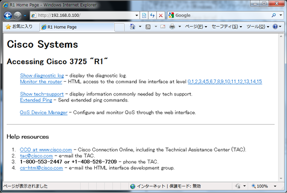
ではブラウザよりhttp://192.168.0.100/に接続します。ユーザ認証を促すプロンプトが表示されますが、level_15_accessのサーバと表示されることに注意してください。

Http1_2

ユーザ名は無し、パスワードはenableパスワードを入力することでログイン出来ます。

Http2

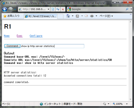
画面上のリンク、Monitor the routerを利用することでブラウザ上からIOSのコマンドを実行することが可能です。

Http3

現在の設定ではアクセス制限がなく、望ましい状態とは言えません。下記はaccess-listを利用し、192.168.0.0/24からのみアクセス出来るようにする例です。

R1(config)#access-list 1 permit 192.168.0.0 0.0.0.255
R1(config)#ip http access-class 1
R1(config)#do sh ip http server status | i class
HTTP server access class: 1

次にユーザ名を利用した認証を確認します。まずユーザciscoをパスワードciscoで作成します。下記のようにprivilegeを指定しない場合、privilege levelは1となります。

R1(config)#username cisco secret cisco
R1(config)#do sh run | i username
username cisco secret 5 $1$wLzt$1ERo8cQ7l4xSpjzVTJoMv1

ユーザ認証を有効にするため、ip http authentication localを実行します。

R1(config)#ip http authentication local
R1(config)#do sh ip http server status | i method
HTTP server authentication method: local

この状態でデバグを有効にし、ログインを実行するとどうなるか確認します。

R1#debug ip http authentication
HTTP Server Authentication debugging is on

認証に必要なレベル15ではないためログインは失敗し、下記のように表示されます。

Apr 11 06:37:46.139: HTTP: Authentication failed for level 15

ここでユーザciscoのprivilegeを15に変更します。

R1(config)#username cisco privilege 15
R1(config)#do sh run | i username
username cisco privilege 15 secret 5 $1$wLzt$1ERo8cQ7l4xSpjzVTJoMv1

問題なくログイン出来るようになりました。

Apr 11 06:40:20.423: HTTP: Priv level granted 15

http serverのパスを指定し、その場所にファイルを置くとそのままブラウザで表示可能です。

R1(config)#ip http path flash:
R1(config)#do sh ip http server status | i path
HTTP server base path: flash:

コマンドの結果はredirectを利用すると直接指定した場所に保存できます。

R1#show ip http server statistics | redirect flash:http.txt

上記のファイルは http://192.168.0.100/http.txt で表示可能です。このように、普通のWebサーバとして出来ることが分かります。

Http4_2

カテゴリ:

今回はRIPの認証を確認します。R2とR3はシリアルケーブルで直接接続(23.23.23.0/24)されています。

R2(config)#do sh ip int b
Interface                  IP-Address      OK? Method Status                Protocol
Serial1/2                  23.23.23.2      YES manual up                    up
Loopback0                  17.17.2.2       YES NVRAM  up                    up

R3(config)#do sh ip int b
Interface                  IP-Address      OK? Method Status                Protocol
Serial1/3                  23.23.23.3      YES manual up                    up
Loopback0                  17.17.3.3       YES NVRAM  up                    up

R2(config)#do pin 23.23.23.3

Type escape sequence to abort.
Sending 5, 100-byte ICMP Echos to 23.23.23.3, timeout is 2 seconds:
!!!!!
Success rate is 100 percent (5/5), round-trip min/avg/max = 8/26/72 ms

まず認証なしでRIPを設定します。CCIE(R&S)ではRIPはバージョン2のみの利用ですので、version 2は必須コマンドです。

R2(config)#router rip
R2(config-router)#version 2
R2(config-router)#no auto-summary
R2(config-router)#network 23.23.23.2
R2(config-router)#network 17.17.2.2

OSPFのように、インターフェイスのIPアドレスをそのまま入力してもクラスフルのネットワークアドレスに自動的に置き換わる点に注意してください。

R2(config-router)#do sh run | s rip
router rip
version 2
network 17.0.0.0
network 23.0.0.0
no auto-summary

RIPの設定を確認するには"show ip protocols"や"show ip rip database"を使います。

"show ip protocols"によりバージョン2が利用されていることや、指定したネットワークが有効であることが確認できます。

R2#show ip protocols
Routing Protocol is "rip"
  Outgoing update filter list for all interfaces is not set
  Incoming update filter list for all interfaces is not set
  Sending updates every 30 seconds, next due in 10 seconds
  Invalid after 180 seconds, hold down 180, flushed after 240
  Redistributing: rip
  Default version control: send version 2, receive version 2
    Interface             Send  Recv  Triggered RIP  Key-chain
    Serial1/2             2     2
    Loopback0             2     2
  Automatic network summarization is not in effect
  Maximum path: 4
  Routing for Networks:
    17.0.0.0
    23.0.0.0
  Routing Information Sources:
    Gateway         Distance      Last Update
  Distance: (default is 120)

"show ip rip database"では、現在自分のネットワークしか表示されていないことが分かります。

R2#show ip rip database
17.0.0.0/8    auto-summary
17.17.2.0/24    directly connected, Loopback0
23.0.0.0/8    auto-summary
23.23.23.0/24    directly connected, Serial1/2

デバグを有効にして、同じコマンドをR3にも入力します。しばらくするとR2からのアップデートが確認できます。

R3#debug ip rip
R3(config-router)#do sh run | s rip
router rip
version 2
network 17.0.0.0
network 23.0.0.0
no auto-summary

Apr  4 07:02:06.631: RIP: received v2 update from 23.23.23.2 on Serial1/3
Apr  4 07:02:06.635:      17.17.2.0/24 via 0.0.0.0 in 1 hops

R2で確認するとRouting Information SourcesにR3のIPアドレスが表示されることが分かります。

R2#show ip protocols | begin Sources
  Routing Information Sources:
    Gateway         Distance      Last Update
    23.23.23.3           120      00:00:23
  Distance: (default is 120)

R3のLo0のネットワークアドレスが追加されています。

R2#show ip rip database
17.0.0.0/8    auto-summary
17.17.2.0/24    directly connected, Loopback0
17.17.3.0/24
    [1] via 23.23.23.3, 00:00:12, Serial1/2
23.0.0.0/8    auto-summary
23.23.23.0/24    directly connected, Serial1/2

では認証を利用するにあたり、キーチェーンを作成します。ここではキーチェーン名を"RIP"としキー番号は"1"としました。キーの文字列は"CISCO"です。同じものをR3でも作成します。キーの文字列の最後に余計なスペースが入ると認証エラーとなりますので注意してください。

R2(config)#key chain RIP
R2(config-keychain)#key 1
R2(config-keychain-key)#key-string CISCO
R2(config-keychain-key)#do sh key chain
Key-chain RIP:
    key 1 -- text "CISCO"
        accept lifetime (always valid) - (always valid) [valid now]
        send lifetime (always valid) - (always valid) [valid now]

まずテキストモードで認証を有効にしてみます。認証はテキストモードが初期値のため、"ip rip authentication mode text"は入れても入れなくても同じです。

R2(config-keychain-key)#int s1/2
R2(config-if)#ip rip authentication key-chain RIP

R2(config-if)#do sh ip prot | b Interface
    Interface             Send  Recv  Triggered RIP  Key-chain
    Serial1/2             2     2                    RIP
    Loopback0             2     2

この時、R3では下記のように表示されます。

Apr  4 07:30:40.923: RIP: ignored v2 packet from 23.23.23.2 (invalid authentication)

R3でも認証を有効にしてみます、テキストモードのためキーの文字列"CISCO"がそのまま表示されることが分かります。

R3(config-router)#int s1/3
R3(config-if)#ip rip authentication key-chain RIP

Apr  4 07:32:04.659: RIP: received packet with text authentication CISCO
Apr  4 07:32:04.659: RIP: ignored v2 packet from 23.23.23.2 (invalid authentication)

より望ましい認証である、MD5モードに変更します。

R2(config)#int s1/2
R2(config-if)#ip rip authentication mode md5

R3(config)#int s1/3
R3(config-if)#ip rip authentication mode md5

確かにMD5が利用されていることが分かります。RIPではこのようにdebugコマンドを利用して、認証を確認します。

Apr  4 07:52:35.035: RIP: received packet with MD5 authentication

カテゴリ:

今回はEIGRPの認証を確認します。R2とR3はシリアルケーブルで接続されています。

R2#show ip interface brief
Interface                  IP-Address      OK? Method Status                Protocol
Serial1/2                  23.23.23.2      YES manual up                    up
Loopback0                  17.17.2.2       YES NVRAM  up                    up

R3#show ip interface brief
Interface                  IP-Address      OK? Method Status                Protocol
Serial1/3                  23.23.23.3      YES manual up                    up
Loopback0                  17.17.3.3       YES NVRAM  up                    up

EIGRPの設定は下記のようになっています。

R2#show running-config | section eigrp
router eigrp 100
network 0.0.0.0
no auto-summary
eigrp router-id 17.17.2.2

R3#show running-config | section eigrp
ip authentication mode eigrp 100 md5
router eigrp 100
network 0.0.0.0
no auto-summary
eigrp router-id 17.17.3.3

R2はR3と接続していることが確認できます。

R2#show ip eigrp neighbors
IP-EIGRP neighbors for process 100
H   Address                 Interface       Hold Uptime   SRTT   RTO  Q  Seq
                                            (sec)         (ms)       Cnt Num
0   23.23.23.3              Se1/2             13 00:00:25    1  5000  2  0

R2#show ip route eigrp
     17.0.0.0/24 is subnetted, 2 subnets
D       17.17.3.0 [90/2297856] via 23.23.23.3, 00:00:07, Serial1/2

認証が利用されているかどうかを調べるには"show ip eigrp interfaces detail"が便利です。現在はR2とR3の間で認証は利用されていません。

R2#show ip eigrp interfaces detail s1/2
IP-EIGRP interfaces for process 100

                        Xmit Queue   Mean   Pacing Time   Multicast    Pending
Interface        Peers  Un/Reliable  SRTT   Un/Reliable   Flow Timer   Routes
Se1/2              1        0/0        34       0/15         151           0
  Hello interval is 5 sec
  Next xmit serial <none>
  Un/reliable mcasts: 0/0  Un/reliable ucasts: 3/82
  Mcast exceptions: 0  CR packets: 0  ACKs suppressed: 10
  Retransmissions sent: 65  Out-of-sequence rcvd: 2
  Authentication mode is not set
  Use unicast

EIGRPで認証を利用するには、まずキーチェーンを作成します。R2とR3で同じものを作成します。ここではキーチェーン名を"EIGRP"としキー番号は"1"としました。キーの文字列は"CISCO"です。

R2(config)#key chain EIGRP
R2(config-keychain)#key 1
R2(config-keychain-key)#key-string CISCO

キーチェーンを作成する際にありがちなミスとして、文字列の最後にスペースを加えてしまうというものがあります。見た目上は同じでも異なる文字列と認識され、認証が失敗しますので注意してください。このミスを防ぐため、"show key chain"で確認を行います。下記の例ではWITHSPACEの最後にスペースがあることが分かります。

R2#show key chain
Key-chain EIGRP:
    key 1 -- text "CISCO"
        accept lifetime (always valid) - (always valid) [valid now]
        send lifetime (always valid) - (always valid) [valid now]
Key-chain WITHSPACE:
    key 1 -- text "CISCO "
        accept lifetime (always valid) - (always valid) [valid now]
        send lifetime (always valid) - (always valid) [valid now]

R3でデバグを有効にします。

R3#debug eigrp packets
EIGRP Packets debugging is on
    (UPDATE, REQUEST, QUERY, REPLY, HELLO, IPXSAP, PROBE, ACK, STUB, SIAQUERY, SIAREPLY)
R3#

R2のs1/2で認証をを有効にします。

R2(config)#int s1/2
R2(config-if)#ip authentication key-chain eigrp 100 EIGRP
R2(config-if)#ip authentication mode eigrp 100 md5

R3で認証を有効にしていない状態では下記のように表示されます。

Mar 28 11:05:03.178: EIGRP: Serial1/3: ignored packet from 23.23.23.2, opcode = 5 (authentication off or key-chain missing)
Mar 28 11:05:03.182: EIGRP: Dropping peer, invalid authentication
Mar 28 11:05:03.186: EIGRP: Sending HELLO on Serial1/3
Mar 28 11:05:03.186:   AS 100, Flags 0x0, Seq 0/0 idbQ 0/0 iidbQ un/rely 0/0
Mar 28 11:05:03.198: %DUAL-5-NBRCHANGE: IP-EIGRP(0) 100: Neighbor 23.23.23.2 (Serial1/3) is down: Auth failure

R3でも認証を有効にします。するとR2とR3の再接続が確認できます。

R3(config)#int s1/3
R3(config-if)#ip authentication key-chain eigrp 100 EIGRP
R3(config-if)#ip authentication mode eigrp 100 md5

Mar 28 11:07:06.974: EIGRP: received packet with MD5 authentication, key id = 1
Mar 28 11:07:06.974: EIGRP: Received HELLO on Serial1/3 nbr 23.23.23.2

確認すると、確かに認証を利用していることが表示されます。

R2#show ip eigrp interfaces detail s1/2
IP-EIGRP interfaces for process 100

                        Xmit Queue   Mean   Pacing Time   Multicast    Pending
Interface        Peers  Un/Reliable  SRTT   Un/Reliable   Flow Timer   Routes
Se1/2              1        0/0        15       0/15          95           0
  Hello interval is 5 sec
  Next xmit serial <none>
  Un/reliable mcasts: 0/0  Un/reliable ucasts: 7/90
  Mcast exceptions: 0  CR packets: 0  ACKs suppressed: 14
  Retransmissions sent: 66  Out-of-sequence rcvd: 4
  Authentication mode is md5,  key-chain is "EIGRP"
  Use unicast

カテゴリ:

今回はOSPFの認証を確認していきます。まず下記のようにR2とR3のインターフェイスが設定してあります。

R2(config-router)#do sh ip int b
Interface                  IP-Address      OK? Method Status                Protocol
Serial1/2                  23.23.23.2      YES manual up                    up
Loopback0                  17.17.2.2       YES NVRAM  up                    up   

R3(config-router)#do sh ip int b
Interface                  IP-Address      OK? Method Status                Protocol
Serial1/3                  23.23.23.3      YES manual up                    up 
Loopback0                  17.17.3.3       YES NVRAM  up                    up

OSPFでそれぞれのシリアルとループバックアドレスアドレスを有効にしました。

R2(config-router)#do sh run | s ospf
router ospf 1
router-id 17.17.2.2
log-adjacency-changes
network 17.17.2.2 0.0.0.0 area 0
network 23.23.23.2 0.0.0.0 area 0

R3(config-router)#do sh run | s ospf
router ospf 1
router-id 17.17.3.3
log-adjacency-changes
network 17.17.3.3 0.0.0.0 area 0
network 23.23.23.3 0.0.0.0 area 0

ここから認証を設定していきます。まずR3でデバグを有効にして、状態を確認できるようにします。

R3#debug ip ospf adj
OSPF adjacency events debugging is on

R2で平文(Simple password authentication)の認証を有効にします。

R2(config-router)#int s1/2
R2(config-if)#ip ospf authentication

R3にはR2が利用しているのがtype 1であると、表示されることが分かります。

R3#
Mar 21 06:18:16.387: OSPF: Rcv pkt from 23.23.23.2, Serial1/3 : Mismatch Authentication type. Input packet specified type 1, we use type 0

次にR2でパスワードを指定します。ここでは"CISCO"としました。

R2(config-if)#ip ospf authentication-key CISCO

R3でも平文での認証を有効にします。

R3(config-router)#int s1/3
R3(config-if)#ip ospf authentication

デバグの内容が変化することが分かります。

R3(config-if)#
Mar 21 06:20:00.531: OSPF: Rcv pkt from 23.23.23.2, Serial1/3 : Mismatch Authentication Key - Clear Text

R3でパスワードを指定すると認証が有効となり、隣接関係が形成されます。

R3(config-if)#ip ospf authentication-key CISCO

Mar 21 06:20:38.019: OSPF: Synchronized with 17.17.2.2 on Serial1/3, state FULL

R3(config-if)#do sh ip os int s1/3
Serial1/3 is up, line protocol is up
  Internet Address 23.23.23.3/24, Area 0
〜略〜
  Simple password authentication enabled

R2で認証方法をMD5(Cryptographic authentication)に変更してみます。

R2(config-if)#ip ospf authentication message-digest

R3にはR2が利用しているのがtype 2であると、表示されることが分かります。

R3#
Mar 21 06:23:39.491: OSPF: Rcv pkt from 23.23.23.2, Serial1/3 : Mismatch Authentication type. Input packet specified type 2, we use type 1

R3でも認証方法をMD5に変更します。

R3(config-if)#ip ospf authentication message-digest

Mar 21 06:25:56.643: OSPF: Send with youngest Key 0
Mar 21 06:26:02.211: OSPF: Rcv pkt from 23.23.23.2, Serial1/3 : Mismatch Authentication Key - No message digest key 1 on interface

するとこの時点で隣接関係が形成されたことが確認できます。

R3(config-if)#do sh ip os nei

Neighbor ID     Pri   State           Dead Time   Address         Interface
17.17.2.2         0   FULL/  -        00:00:39    23.23.23.2      Serial1/3

このキーを設定していない状態では、下記のように表示されます。もちろん、設定としてこれは不完全です。

R3(config-if)#do sh ip os int s1/3
Serial1/3 is up, line protocol is up
  Internet Address 23.23.23.3/24, Area 0
〜略〜
  Message digest authentication enabled
      No key configured, using default key id 0

次にキーを設定します。ここでは"CCNA"を利用します。

R2(config-if)#ip ospf message-digest-key 1 md5 CCNA

R3でのデバグです。もちろんこの時点では隣接関係は壊れています。

Mar 21 07:10:50.175: OSPF: Send with youngest Key 0
Mar 21 07:10:53.375: OSPF: Rcv pkt from 23.23.23.2, Serial1/3 : Mismatch Authentication Key - No message digest key 1 on interface

R3にもキーを設定します。

R3(config-if)#ip ospf message-digest-key 1 md5 CCNA

これにより隣接関係が再形成されます。

R3(config-if)#do sh ip os int s1/3
Serial1/3 is up, line protocol is up
  Internet Address 23.23.23.3/24, Area 0
〜略〜
  Message digest authentication enabled
    Youngest key id is 1

今回はインターフェイスでの認証方法を指定しましたが、エリア全体で指定も可能です。まず先程の認証の指定を無効にします。

R2(config-if)#no ip ospf authentication message-digest
R2(config-if)#no ip ospf authentication-key CISCO

R3(config-if)#no ip ospf authentication message-digest
R3(config-if)#no ip ospf authentication-key CISCO

OSPFのプロセスで認証を有効にします。

R2(config-if)#router ospf 1
R2(config-router)#area 0 authentication message-digest

R3(config-if)#router ospf 1
R3(config-router)#area 0 authentication message-digest

確認すると同じように、MD5での認証が有効であることが分かります。

R3(config-router)#do sh ip os int s1/3
Serial1/3 is up, line protocol is up
  Internet Address 23.23.23.3/24, Area 0
〜略〜
  Message digest authentication enabled
    Youngest key id is 1

カテゴリ:

今回は前回のIP Precedenceの確認方法をふまえて、ポリシーマップを利用してみます。R1はR2を経由してR3と接続されており、EIGRPでルーティングが設定されています。

R3#sh ip interface brief
Interface                  IP-Address      OK? Method Status                Protocol
Serial1/3                  23.23.23.3      YES manual up                    up      
Loopback0                  17.17.3.3       YES NVRAM  up                    up

R3#show ip route eigrp
     17.0.0.0/24 is subnetted, 3 subnets
D       17.17.1.0 [90/2300416] via 23.23.23.2, 01:43:35, Serial1/3
D       17.17.2.0 [90/2297856] via 23.23.23.2, 01:52:36, Serial1/3
     12.0.0.0/24 is subnetted, 1 subnets
D       12.12.12.0 [90/2172416] via 23.23.23.2, 01:52:36, Serial1/3

R1のLo0にpingが実行出来ることを確認します。

R3#ping 17.17.1.1

Type escape sequence to abort.
Sending 5, 100-byte ICMP Echos to 17.17.1.1, timeout is 2 seconds:
!!!!!
Success rate is 100 percent (5/5), round-trip min/avg/max = 12/17/32 ms

ここでR1にアクセスリストを作成します。まずEIGRPは全て許可します。次にprecedence値がflash(3)であれば許可とし、それ以外は拒否としました。ちなみにflashを選択したことに深い意味はありません。

R1(config)#ip access-list extended PRECEDENCE
R1(config-ext-nacl)#permit eigrp any any
R1(config-ext-nacl)#permit ip any any precedence flash log
R1(config-ext-nacl)#deny ip any any

R1#show ip access-lists
Extended IP access list PRECEDENCE
    10 permit eigrp any any
    20 permit ip any any precedence flash log
    30 deny ip any any

これをF0/0に適用します。

R1(config)#interface f0/0
R1(config-if)#ip access-group PRECEDENCE in

R1#show ip access-lists interface f0/0
Extended IP access list PRECEDENCE in
    10 permit eigrp any any (15 matches)
    20 permit ip any any precedence flash log
    30 deny ip any any

この設定によりR3からのpingは実行できなくなります。

R3#ping 17.17.1.1

Type escape sequence to abort.
Sending 5, 100-byte ICMP Echos to 17.17.1.1, timeout is 2 seconds:
U.U.U
Success rate is 0 percent (0/5)

次にR2で特定のパケットにprecedence値のflashを設定するためのポリシーマップを作ります。まずアクセスリストを作ります。R3のLo0(17.17.3.3)を許可し、S1/3(23.23.23.3)を拒否します。

R2(config)#ip access-list standard FROM_R3
R2(config-std-nacl)#permit host 17.17.3.3
R2(config-std-nacl)#deny host 23.23.23.3

R2#show ip access-lists FROM_R3
Standard IP access list FROM_R3
    10 permit 17.17.3.3
    20 deny   23.23.23.3

次にクラスマップを作ります。

R2(config)#class-map C_FROM_R3
R2(config-cmap)#match access-group name FROM_R3

R2#show class-map C_FROM_R3
Class Map match-all C_FROM_R3 (id 2)
   Match access-group name FROM_R3

最後にポリシーマップを作ります。

R2(config)#policy-map P_FROM_R3
R2(config-pmap)#class C_FROM_R3
R2(config-pmap-c)#set ip precedence ?
  <0-7>           Precedence value
  critical        Set packets with critical precedence (5)
  flash           Set packets with flash precedence (3)
  flash-override  Set packets with flash override precedence (4)
  immediate       Set packets with immediate precedence (2)
  internet        Set packets with internetwork control precedence (6)
  network         Set packets with network control precedence (7)
  priority        Set packets with priority precedence (1)
  routine         Set packets with routine precedence (0)
R2(config-pmap-c)#set ip precedence flash

R2#show policy-map P_FROM_R3
  Policy Map P_FROM_R3
    Class C_FROM_R3
      set ip precedence 3

ポリシーマップをR3に接続されたS1/2に適用します。

R2(config)#interface s1/2
R2(config-if)#service-policy input P_FROM_R3

R2#show policy-map interface s1/2
Serial1/2

  Service-policy input: P_FROM_R3

    Class-map: C_FROM_R3 (match-all)
      0 packets, 0 bytes
      5 minute offered rate 0 bps, drop rate 0 bps
      Match: access-group name FROM_R3
      QoS Set
        precedence 3
          Packets marked 0

    Class-map: class-default (match-any)
      4 packets, 256 bytes
      5 minute offered rate 0 bps, drop rate 0 bps
      Match: any

ここでR3よりpingを実行しますが、エラーとなります。R2のアクセスリストを見るとR3はS1/3(23.23.23.3)を使っていることが分かります。

R2#show ip access-lists FROM_R3
Standard IP access list FROM_R3
    10 permit 17.17.3.3
    20 deny   23.23.23.3 (56 matches)

次にソースアドレスをLo0(17.17.3.3)で指定して実行すると成功することが分かります。

R3#ping 17.17.1.1 source loopback 0

Type escape sequence to abort.
Sending 5, 100-byte ICMP Echos to 17.17.1.1, timeout is 2 seconds:
Packet sent with a source address of 17.17.3.3
!!!!!
Success rate is 100 percent (5/5), round-trip min/avg/max = 12/15/20 ms

R2でポリシーマップを確認すると、パケットにprecedence値が設定されたことが分かります。

R2#show policy-map interface s1/2
Serial1/2

  Service-policy input: P_FROM_R3

    Class-map: C_FROM_R3 (match-all)
      5 packets, 520 bytes
      5 minute offered rate 0 bps, drop rate 0 bps
      Match: access-group name FROM_R3
      QoS Set
        precedence 3
          Packets marked 5

    Class-map: class-default (match-any)
      108 packets, 7312 bytes
      5 minute offered rate 0 bps, drop rate 0 bps
      Match: any

R1でアクセスリストを確認するとprecedence flashが許可されたことが分かります。

R1#
Mar 13 08:58:36.659: %SEC-6-IPACCESSLOGDP: list PRECEDENCE permitted icmp 17.17.3.3 -> 17.17.1.1 (0/0), 5 packets
R1#show ip access-lists interface f0/0
Extended IP access list PRECEDENCE in
    10 permit eigrp any any (1410 matches)
    20 permit ip any any precedence flash log (5 matches)
    30 deny ip any any (15 matches)

カテゴリ:

QoSの設定ではIP Precedence(Type of Serviceの先頭3ビット)やDSCP(Type of Serviceの先頭6ビット)を使いますが、実際のパケットに設定されていることを、どのようにして確認すればいいのでしょうか。ここではアクセスリストを利用する方法を紹介ます。

拡張アクセスリストを利用します。matchで該当のprecedenceを指定しますが、最後にlogを利用することで確認が用意になります。最終行のpermitを省くとパケットは全く通過できなくなるので注意が必要です。

R1(config)#ip access-list extended CHECK_PRECEDENCE
R1(config-ext-nacl)#deny ip any any precedence ?
  <0-7>           Precedence value
  critical        Match packets with critical precedence (5)
  flash           Match packets with flash precedence (3)
  flash-override  Match packets with flash override precedence (4)
  immediate       Match packets with immediate precedence (2)
  internet        Match packets with internetwork control precedence (6)
  network         Match packets with network control precedence (7)
  priority        Match packets with priority precedence (1)
  routine         Match packets with routine precedence (0)

R1(config-ext-nacl)#deny ip any any precedence priority ?
  fragments   Check non-initial fragments
  log         Log matches against this entry
  log-input   Log matches against this entry, including input interface
  option      Match packets with given IP Options value
  time-range  Specify a time-range
  tos         Match packets with given TOS value
  ttl         Match packets with given TTL value
  <cr>

R1(config-ext-nacl)#deny ip any any precedence priority log
R1(config-ext-nacl)#deny ip any any precedence immediate log
R1(config-ext-nacl)#permit ip any any
R1(config-ext-nacl)#do show ip access-lists CHECK_PRECEDENCE
Extended IP access list CHECK_PRECEDENCE
    10 deny ip any any precedence priority log
    20 deny ip any any precedence immediate log
    30 permit ip any any
R1(config-ext-nacl)#int f0/0
R1(config-if)#ip access-group CHECK_PRECEDENCE in
R1(config-if)#do sh ip int f0/0 | i Inbound
  Inbound  access list is CHECK_PRECEDENCE

もちろん、通常のpingはそのまま実行されます。

R2#ping 12.12.12.1

Type escape sequence to abort.
Sending 5, 100-byte ICMP Echos to 12.12.12.1, timeout is 2 seconds:
!!!!!
Success rate is 100 percent (5/5), round-trip min/avg/max = 8/10/12 ms

ではこのアクセスリストにTOS値を指定してpingを実行します。外部からのパケットでないとアクセスリストは反応しないので注意してください。ここでは隣接するR2から実行します。

まずType of serviceで32を指定して実行します。32は001となるため、IP Precedenceのpriorityが利用されます。

R2#ping
Protocol [ip]:
Target IP address: 12.12.12.1
Repeat count [5]:
Datagram size [100]:
Timeout in seconds [2]:
Extended commands [n]: y
Source address or interface:
Type of service [0]: 32
Set DF bit in IP header? [no]:
Validate reply data? [no]:
Data pattern [0xABCD]:
Loose, Strict, Record, Timestamp, Verbose[none]:
Sweep range of sizes [n]:
Type escape sequence to abort.
Sending 5, 100-byte ICMP Echos to 12.12.12.1, timeout is 2 seconds:
U.U.U
Success rate is 0 percent (0/5)

R1(config-if)#
Mar  7 07:09:54.575: %SEC-6-IPACCESSLOGDP: list CHECK_PRECEDENCE denied icmp 12.12.12.2 -> 12.12.12.1 (0/0), 1 packet
Mar  7 07:15:18.459: %SEC-6-IPACCESSLOGDP: list CHECK_PRECEDENCE denied icmp 12.12.12.2 -> 12.12.12.1 (0/0), 4 packets
R1(config-if)#do show ip access-lists CHECK_PRECEDENCE
Extended IP access list CHECK_PRECEDENCE
    10 deny ip any any precedence priority log (5 matches)
    20 deny ip any any precedence immediate log
    30 permit ip any any (627 matches)

次にType of service 64を指定して実行します。64は010となるため、IP Precedenceのimmediateが利用されます。違いを分かりやすくするために、リピート回数を4にしています。

R2#ping
Protocol [ip]:
Target IP address: 12.12.12.1
Repeat count [5]: 4
Datagram size [100]:
Timeout in seconds [2]:
Extended commands [n]: y
Source address or interface:
Type of service [0]: 64
Set DF bit in IP header? [no]:
Validate reply data? [no]:
Data pattern [0xABCD]:
Loose, Strict, Record, Timestamp, Verbose[none]:
Sweep range of sizes [n]:
Type escape sequence to abort.
Sending 4, 100-byte ICMP Echos to 12.12.12.1, timeout is 2 seconds:
U.U.
Success rate is 0 percent (0/4)

R1(config-if)#
Mar  7 07:23:18.459: %SEC-6-IPACCESSLOGDP: list CHECK_PRECEDENCE denied icmp 12.12.12.2 -> 12.12.12.1 (0/0), 4 packets
R1(config-if)#do show ip access-lists CHECK_PRECEDENCE
Extended IP access list CHECK_PRECEDENCE
    10 deny ip any any precedence priority log (5 matches)
    20 deny ip any any precedence immediate log (4 matches)
    30 permit ip any any (813 matches)

同じような手順で、アクセスリストでDSCPを利用することも可能です。

R1(config-if)# ip access-list extended CHECK_PRECEDENCE
R1(config-ext-nacl)#25 deny ip any any dscp ?
  <0-63>   Differentiated services codepoint value
  af11     Match packets with AF11 dscp (001010)
  af12     Match packets with AF12 dscp (001100)
  af13     Match packets with AF13 dscp (001110)
  af21     Match packets with AF21 dscp (010010)
  af22     Match packets with AF22 dscp (010100)
  af23     Match packets with AF23 dscp (010110)
  af31     Match packets with AF31 dscp (011010)
  af32     Match packets with AF32 dscp (011100)
  af33     Match packets with AF33 dscp (011110)
  af41     Match packets with AF41 dscp (100010)
  af42     Match packets with AF42 dscp (100100)
  af43     Match packets with AF43 dscp (100110)
  cs1      Match packets with CS1(precedence 1) dscp (001000)
  cs2      Match packets with CS2(precedence 2) dscp (010000)
  cs3      Match packets with CS3(precedence 3) dscp (011000)
  cs4      Match packets with CS4(precedence 4) dscp (100000)
  cs5      Match packets with CS5(precedence 5) dscp (101000)
  cs6      Match packets with CS6(precedence 6) dscp (110000)
  cs7      Match packets with CS7(precedence 7) dscp (111000)
  default  Match packets with default dscp (000000)
  ef       Match packets with EF dscp (101110)

R1(config-ext-nacl)#25 deny ip any any dscp af43 log

R2よりTOS値152(100110)でpingをリピート回数6で実行しました。

R1(config-ext-nacl)#
Mar  7 07:30:18.463: %SEC-6-IPACCESSLOGDP: list CHECK_PRECEDENCE denied icmp 12.12.12.2 -> 12.12.12.1 (0/0), 6 packets
R1(config-ext-nacl)#do show ip access-lists CHECK_PRECEDENCE
Extended IP access list CHECK_PRECEDENCE
    10 deny ip any any precedence priority log (5 matches)
    20 deny ip any any precedence immediate log (8 matches)
    25 deny ip any any dscp af43 log (6 matches)
    30 permit ip any any (1077 matches)

カテゴリ:

3つのインターフェイスにIPアドレスを設定します。ここではあえてマスク値を/24以外で設定しました。

interface Serial1/0
ip address 192.168.3.1 255.255.255.128
!
interface Serial1/1
ip address 192.168.33.1 255.255.255.192
!
interface Serial1/2
ip address 192.168.133.1 255.255.255.224

IPアドレスを設定した後に設定を確認しますが、show ip interface briefではマスク値は表示されません。

R3#show ip interface brief
Interface                  IP-Address      OK? Method Status                Protocol
Serial1/0                  192.168.3.1     YES manual up                    down
Serial1/1                  192.168.33.1    YES manual up                    down
Serial1/2                  192.168.133.1   YES manual up                    down

IPアドレスを設定したにもかかわらず通信が出来ない場合、マスク値が意図したものになっていない場合がままあります。マスク値の確認はshow ip interfaceを利用します。

R3#show ip interface
Serial1/0 is up, line protocol is down
  Internet address is 192.168.3.1/25
  Broadcast address is 255.255.255.255
〜略〜

ただこのまま実行すると上記の様に、不要な情報まで大量に表示されます。ここでincludeと|を利用することで、必要な行のみを抜き出すことが可能です。

R3#show ip interface | include is up|Internet address
Serial1/0 is up, line protocol is down
  Internet address is 192.168.3.1/25
Serial1/1 is up, line protocol is down
  Internet address is 192.168.33.1/26
Serial1/2 is up, line protocol is down
  Internet address is 192.168.133.1/27

またBGPの学習時など、たくさんのIPアドレスを設定する必要がある場合はsecondary addressが便利です。一つのインターフェイスに複数のIPアドレスを設定することが可能です。

R2(config)#interface loopback 200
R2(config-if)#ip address 192.168.0.2 255.255.255.0
R2(config-if)#ip address 192.168.1.2 255.255.255.0 ?
  secondary  Make this IP address a secondary address
R2(config-if)#ip address 192.168.1.2 255.255.255.0 secondary
R2(config-if)#ip address 192.168.2.2 255.255.255.0 secondary
R2(config-if)#ip address 192.168.3.2 255.255.255.0 secondary

R2#show running-config interface loopback 200
Building configuration...

Current configuration : 211 bytes
!
interface Loopback200
ip address 192.168.1.2 255.255.255.0 secondary
ip address 192.168.2.2 255.255.255.0 secondary
ip address 192.168.3.2 255.255.255.0 secondary
ip address 192.168.0.2 255.255.255.0

設定の確認にはshow ip interfaceを利用しますが、includeを使うことで見やすい形式にしています。

R2#show ip interface loopback 200 | include Internet|Secondary
  Internet address is 192.168.0.2/24
  Secondary address 192.168.1.2/24
  Secondary address 192.168.2.2/24
  Secondary address 192.168.3.2/24

そのままBGPで利用出来ることが分かります。

R2(config)#router bgp 200
R2(config-router)#network 192.168.0.0 mask 255.255.255.0
R2(config-router)#network 192.168.1.0 mask 255.255.255.0
R2(config-router)#network 192.168.2.0 mask 255.255.255.0
R2(config-router)#network 192.168.3.0 mask 255.255.255.0

R2#show ip bgp
BGP table version is 5, local router ID is 17.17.2.2
Status codes: s suppressed, d damped, h history, * valid, > best, i - internal,
              r RIB-failure, S Stale
Origin codes: i - IGP, e - EGP, ? - incomplete

   Network          Next Hop            Metric LocPrf Weight Path
*> 192.168.0.0      0.0.0.0                  0         32768 i
*> 192.168.1.0      0.0.0.0                  0         32768 i
*> 192.168.2.0      0.0.0.0                  0         32768 i
*> 192.168.3.0      0.0.0.0                  0         32768 i

カテゴリ:

pingコマンドでネットワークの疎通を確認しますが、sourceを利用して送信元のインターフェイスやIPアドレスを指定することが出来ます。

R1#ping 192.168.1.1 ?
〜略〜
  source    specify source address or name
〜略〜

現在R1とR2は12.12.12.0/24で直接接続されています。

R1#show ip interface brief
Interface                  IP-Address      OK? Method Status                Protocol
FastEthernet0/0            12.12.12.1      YES manual up                    up      
FastEthernet0/1            1.1.1.1         YES manual up                    up      
Loopback0                  17.17.1.1       YES NVRAM  up                    up      

R2#show ip interface brief
Interface                  IP-Address      OK? Method Status                Protocol
FastEthernet0/0            12.12.12.2      YES manual up                    up      
Loopback0                  17.17.2.2       YES NVRAM  up                    up

まずR2のF0/0へpingを実行します。この時点ではルーティングの設定はまだありません。

R1#ping 12.12.12.2

Type escape sequence to abort.
Sending 5, 100-byte ICMP Echos to 12.12.12.2, timeout is 2 seconds:
!!!!!
Success rate is 100 percent (5/5), round-trip min/avg/max = 4/8/12 ms

ここでEIGRPを設定します。

R1(config)#router eigrp 100
R1(config-router)#no auto-summary
R1(config-router)#network 17.17.1.1 0.0.0.0
R1(config-router)#network 12.12.12.1 0.0.0.0

R2(config)#router eigrp 100
R2(config-router)#no auto-summary
R2(config-router)#network 17.17.2.2 0.0.0.0
R2(config-router)#network 12.12.12.2 0.0.0.0

R1がR2とネイバーを確立したことを確認します。

R1#show ip eigrp neighbors
IP-EIGRP neighbors for process 100
H   Address                 Interface       Hold Uptime   SRTT   RTO  Q  Seq
                                            (sec)         (ms)       Cnt Num
0   12.12.12.2              Fa0/0             12 00:00:12    8   300  0  4

この時点でのルーティングテーブルを確認します。

R1#show ip route eigrp
     17.0.0.0/24 is subnetted, 2 subnets
D       17.17.2.0 [90/156160] via 12.12.12.2, 00:02:07, FastEthernet0/0

R2#show ip route eigrp
     17.0.0.0/24 is subnetted, 2 subnets
D       17.17.1.0 [90/156160] via 12.12.12.1, 00:02:16, FastEthernet0/0

R1からpingコマンドを実行する前に、R2でdebugを設定します。

R2#debug ip icmp
ICMP packet debugging is on

ここでpingをR2のLo0に対して実行します。

R1#ping 17.17.2.2

Type escape sequence to abort.
Sending 5, 100-byte ICMP Echos to 17.17.2.2, timeout is 2 seconds:
!!!!!
Success rate is 100 percent (5/5), round-trip min/avg/max = 4/8/16 ms

この時、R2では下記のようなログが表示されます。dstが12.12.12.1であることから、pingはF0/0をソースとして実行されたことが分かります。

R2#
Feb 23 06:07:08.119: ICMP: echo reply sent, src 17.17.2.2, dst 12.12.12.1
Feb 23 06:07:08.135: ICMP: echo reply sent, src 17.17.2.2, dst 12.12.12.1

次にsourceを利用して実行します。ここではLo0(17.17.1.1)を指定しました。

R1#ping 17.17.2.2 source loopback 0

Type escape sequence to abort.
Sending 5, 100-byte ICMP Echos to 17.17.2.2, timeout is 2 seconds:
Packet sent with a source address of 17.17.1.1
!!!!!
Success rate is 100 percent (5/5), round-trip min/avg/max = 4/7/8 ms

R2のログは下記のようになります。確かに17.17.1.1を利用していることが分かります。

Feb 23 06:09:42.091: ICMP: echo reply sent, src 17.17.2.2, dst 17.17.1.1
Feb 23 06:09:42.111: ICMP: echo reply sent, src 17.17.2.2, dst 17.17.1.1

では次にF0/1(1.1.1.1)を利用して実行しますが、失敗します。

R1#ping 17.17.2.2 source fastEthernet 0/1

Type escape sequence to abort.
Sending 5, 100-byte ICMP Echos to 17.17.2.2, timeout is 2 seconds:
Packet sent with a source address of 1.1.1.1
.....
Success rate is 0 percent (0/5)

何故でしょうか。R2では下記のようなログが表示されていることから、パケットが届いており、replyを1.1.1.1に対して送っていることが分かります。

Feb 23 06:15:32.807: ICMP: echo reply sent, src 17.17.2.2, dst 1.1.1.1
Feb 23 06:15:34.811: ICMP: echo reply sent, src 17.17.2.2, dst 1.1.1.1

pingが成功しない理由は、R2のルーティングテーブルに1.1.1.1が載っていないからです。

R2#show ip route 1.1.1.1
% Network not in table

ここでR1のEIGRPでF0/1を有効にします。

R1(config)#router eigrp 100
R1(config-router)#network 1.1.1.1 0.0.0.0

これによりR2のルーティングテーブルに1.1.1.1が載りました。

R2#show ip route 1.1.1.1
Routing entry for 1.1.1.0/24
  Known via "eigrp 100", distance 90, metric 30720, type internal
〜略〜

先程のpingが無事実行出来ます。

R1#ping 17.17.2.2 source fastEthernet 0/1

Type escape sequence to abort.
Sending 5, 100-byte ICMP Echos to 17.17.2.2, timeout is 2 seconds:
Packet sent with a source address of 1.1.1.1
!!!!!
Success rate is 100 percent (5/5), round-trip min/avg/max = 8/8/12 ms

このように、pingが通らない時にはping sourceとdebug ip icmpを利用することで問題点を見つけやすくなります。

カテゴリ:

CCIEの勉強を始めた当初、どつぼに嵌まったのがRIPでのpassive-interfaceの利用方法でした。INEのワークブックを利用していたのですが、RIPの設定で片方のルータにはpassive-interfaceの設定があるにもかかわらず、もう片方にはその設定がないのです。初めは誤植かと思い、INEの掲示板を見ましたが間違ってはいないようでした。そしてしばらくしてやっと理解できたのです…。

ではまずpassive-interfaceコマンドが必要な例です。R2はF0/0でR1に接続され、S1/2でR3に接続されています。そしてR1とのみRIPを利用するとします。

R2#show ip interface brief
Interface                  IP-Address      OK? Method Status                Protocol
FastEthernet0/0            172.16.12.2     YES manual up                    up
Serial1/2                  172.16.23.2     YES manual up                    up

R2(config)#router rip
R2(config-router)#version 2
R2(config-router)#no auto-summary
R2(config-router)#network 172.16.12.2

まずここでのポイントはnetworkコマンドです。RIPではOSPFなどと違い、IPアドレスを指定しても意味がありません。自動的にネットワークアドレスに変換されてしまいます。

R2#show running-config | section rip
router rip
version 2
network 172.16.0.0
no auto-summary

上記のコマンドにより、F0/0だけを有効にしたつもりが結果的にS1/2もRIPを流すという設定になってしまうことが分かります。

R2#show ip protocols
Routing Protocol is "rip"
〜略〜
    Interface             Send  Recv  Triggered RIP  Key-chain
    FastEthernet0/0       2     2
    Serial1/2             2     2
〜略〜
  Routing for Networks:
    172.16.0.0
〜略〜

debugコマンドを実行することで両方のインターフェイスからRIPが流れることが確認できます。

R2#debug ip rip
RIP protocol debugging is on

Feb 16 07:34:44.627: RIP: sending v2 update to 224.0.0.9 via Serial1/2 (172.16.23.2)
Feb 16 07:34:44.631: RIP: build update entries
Feb 16 07:34:44.631:    172.16.12.0/24 via 0.0.0.0, metric 1, tag 0
Feb 16 07:34:48.311: RIP: sending v2 update to 224.0.0.9 via FastEthernet0/0 (172.16.12.2)
Feb 16 07:34:48.315: RIP: build update entries
Feb 16 07:34:48.315:    172.16.23.0/24 via 0.0.0.0, metric 1, tag 0

ここでpassive-interfaceの設定を加えます。するとF0/0のみからRIPが流れるようになります。

R2(config)#router rip
R2(config-router)#passive-interface serial 1/2

Feb 16 07:36:10.367: RIP: sending v2 update to 224.0.0.9 via FastEthernet0/0 (172.16.12.2)
Feb 16 07:36:10.371: RIP: build update entries
Feb 16 07:36:10.371:    172.16.23.0/24 via 0.0.0.0, metric 1, tag 0
Feb 16 07:36:39.751: RIP: sending v2 update to 224.0.0.9 via FastEthernet0/0 (172.16.12.2)
Feb 16 07:36:39.755: RIP: build update entries
Feb 16 07:36:39.755:    172.16.23.0/24 via 0.0.0.0, metric 1, tag 0

次にpassive-interfaceが不要な例です。S1/2のIPアドレスを変更しました。

R2#show ip interface brief
Interface                  IP-Address      OK? Method Status                Protocol
FastEthernet0/0            172.16.12.2     YES manual up                    up
Serial1/2                  192.168.23.2    YES manual up                    up

先程と全く同じRIPの設定を行います。

R2(config)#no router rip
R2(config)#router rip
R2(config-router)#version 2
R2(config-router)#no auto-summary
R2(config-router)#network 172.16.12.2

debugを確認するとRIPが流れているのはF0/0だけであることが分かります。

Feb 16 07:45:29.639: RIP: sending v2 update to 224.0.0.9 via FastEthernet0/0 (172.16.12.2)
Feb 16 07:45:29.643: RIP: build update entries - suppressing null update
Feb 16 07:45:58.779: RIP: sending v2 update to 224.0.0.9 via FastEthernet0/0 (172.16.12.2)
Feb 16 07:45:58.783: RIP: build update entries - suppressing null update

R2#show ip protocols
Routing Protocol is "rip"
〜略〜
    Interface             Send  Recv  Triggered RIP  Key-chain
    FastEthernet0/0       2     2
〜略〜
  Routing for Networks:
    172.16.0.0
〜略〜

なぜpassive-interfaceがなくても、S1/2は対象にならないのでしょうか。それはS1/2に設定されているIPアドレスが異なるネットワーク(192.168.23.0)だからです。当たり前と言えばあまりに当たり前の単純なことですが、passive-interfaceを入れないと意図しないインターフェイスからパケットが流れてしまうという考えに固執している間は中々気づけませんでした。独学の辛いところです。

passive-interfaceを多くのインターフェイスに設定する必要がある場合は、先ずpassive-interface defaultとして全てを無効にし、その後no passive-interfaceで利用するインターフェイスを有効にすると便利です。

R2(config)#router rip
R2(config-router)#version 2
R2(config-router)#no auto-summary
R2(config-router)#passive-interface default
R2(config-router)#no passive-interface fastEthernet 0/0

French Laundryを予約する方法

カテゴリ:

Frenchアメリカで最高のレストランとか、最も予約が取れないレストランと称されるThe French Laundry。幸いなことに無事、予約が取れて訪れることが出来ました。

まず予約方法ですが、正当法としては直接電話するとOpenTableを利用するの二つがあります。

初めは当然のことながらOpenTableで予約を試みましたが、まったく空きが出ません。ここまで空席がないのは初体験で、システムエラーかとも思いましたが、日を変えて何度も試ても結局無駄手間でした。

次は結果的に成功した、直接電話する方法。予約は2ヶ月前の10:00-17:30(太平洋標準時)の間、受け付けています。開始直後の10時に、国際電話をしてみましたが話し中で全くつながりません…。しばらくして現地の夕方にかけ直したらつながりました。

ということで、直接電話がもっとも確実と思われます。ただこの二つ以外の予約方法も色々と研究されているようです。

Restaurant Review: The French Laundry, Yountville

さて無事に予約の日になり、レストランに到着しました。あちこちに書いてあるように、非常に地味で小さな建物です。もとは洗濯屋さんだったとか。

メニューは通常のコースか、ベジタリアンのコースのみ。全部で9皿で、一部分は選択できます。全て繊細な味付けと盛り付け。全米一を実感しました。皿数が多いため、3時間ほどかかります。

そしてここは料理だけでなく、ワインリストもすごい。フランスの三つ星などに行けば当然ながらワインは充実していますが、フランス産が中心です(当たり前ですが)。そしてアメリカの高級レストランではフランス産もアメリカ産も充実している店が多いのですが、ここのリストは半端ではない。

カリフォルニア産で入手困難らしい、Screaming Eagle, Harlan Estate, Dalla Valleなどがあり、フランス産もPetrus, Romane-Conti, 5大シャトーなどの有名どころがヴィンテージ違いでゴロゴロあります。なかなか手に入らないワインを飲みに行くという考えで行く人も多いのかもしれません。ちなみに隣に座っていたアメリカ人6人組(多分夫婦3組)はこれでもかというくらいに赤ワインを開けていました。人事ながら、いくらになったのか気になります…。

このレストランはサンフランシスコ市内からだと車で1時間以上はかかるので、ナパに泊まってタクシーなどで行くことをお勧めします。

アメリカの本屋さんの料理コーナーでは、シェフ Thomas Kellerさんの本が大人気のようでした。

The Essential Thomas Keller: The French Laundry Cookbook / Ad Hoc at Home

カテゴリ:

IOSで利用するコマンドの多くは省略した形で利用できます。例えば"show running-config"は"sh run"に、"configure terminal"は"conf t"で代用できます。この省略形に馴れることで入力の手間を大幅に減らすことが出来ます。

もう一つ便利な方法にdoコマンドがあります。通常、設定以後はshowコマンドで設定を確認しますが、特権モードに戻るのが手間です。しかしdoコマンドを使えば、設定中のモードでそのままshowコマンドなどを実行できます。例えば"do sh run"の様に実行します。

下記はripの設定を認証を含め設定しています。まず全く省略せず、doコマンドを使わない例です。

R1#show ip interface brief
Interface                  IP-Address      OK? Method Status                Protocol
FastEthernet0/0            192.168.12.1    YES manual up                    up      
FastEthernet0/1            unassigned      YES unset  administratively down down   
Serial1/0                  unassigned      YES unset  administratively down down   
Serial1/1                  unassigned      YES unset  administratively down down   
Serial1/2                  unassigned      YES unset  administratively down down   
Serial1/3                  unassigned      YES unset  administratively down down   
Loopback0                  192.168.1.1     YES manual up                    up      
R1#configure terminal
R1(config)#router rip
R1(config-router)#version 2
R1(config-router)#no auto-summary
R1(config-router)#network 192.168.12.1
R1(config-router)#network 192.168.1.1
R1(config-router)#^Z
R1#show ip protocols
Routing Protocol is "rip"
  Outgoing update filter list for all interfaces is not set
  Incoming update filter list for all interfaces is not set
  Sending updates every 30 seconds, next due in 16 seconds
  Invalid after 180 seconds, hold down 180, flushed after 240
  Redistributing: rip
  Default version control: send version 2, receive version 2
    Interface             Send  Recv  Triggered RIP  Key-chain
    FastEthernet0/0       2     2                    RIP            
    Loopback0             2     2                                    
  Automatic network summarization is not in effect
  Maximum path: 4
  Routing for Networks:
    192.168.1.0
    192.168.12.0
  Routing Information Sources:
  1  Gateway         Distance      Last Update
    192.168.12.2         120      00:00:15
  Distance: (default is 120)

R1#configure terminal
R1(config)#key chain RIP
R1(config-keychain)#key 1
R1(config-keychain-key)#key-string CISCO
R1(config-keychain-key)#^Z
R1#show key chain RIP
Key-chain RIP:
    key 1 -- text "CISCO"
        accept lifetime (always valid) - (always valid) [valid now]
        send lifetime (always valid) - (always valid) [valid now]

R1#configure terminal
R1(config)#interface fastEthernet 0/0
R1(config-if)#ip rip authentication key-chain RIP
R1(config-if)#ip rip authentication mode md5
R1(config-if)#^Z
R1#debug ip rip
RIP protocol debugging is on

Feb  4 05:57:23.275: RIP: received packet with MD5 authentication
Feb  4 05:57:23.275: RIP: received v2 update from 192.168.12.2 on FastEthernet0/0
Feb  4 05:57:23.279:      192.168.2.0/24 via 0.0.0.0 in 1 hops
〜略〜

R1#show ip rou rip
R    192.168.2.0/24 [120/1] via 192.168.12.2, 00:00:08, FastEthernet0/0

次に省略形とdoコマンドを併用する例です。大幅に簡略化され、高速に実行出来ることが理解できると思います。

R1#sh ip int b
Interface                  IP-Address      OK? Method Status                Protocol
〜略〜
R1#conf t
R1(config)#router rip
R1(config-router)#no au
R1(config-router)#ver 2
R1(config-router)#net 192.168.12.1
R1(config-router)#net 192.168.1.1
R1(config-router)#do sh ip pro
Routing Protocol is "rip"
〜略〜
R1(config-router)#key ch RIP
R1(config-keychain)#ke 1
R1(config-keychain-key)#key-s CISCO
R1(config-keychain-key)#do sh ke ch RIP
Key-chain RIP:
〜略〜
R1(config-if)#ip rip aut ke RIP
R1(config-if)#ip rip aut m m
R1(config-if)#do deb ip rip
R1(config-if)#do sh ip rou rip
R    192.168.2.0/24 [120/1] via 192.168.12.2, 00:00:13, FastEthernet0/0

カテゴリ:

CCIEの勉強を初めると馴染みのない技術がたくさん出てきます。その中の一つであるSLA(Implement IP Service Level Agreement SLA)は解説も少なく、理解に時間がかかります。ここでは基本的なSLAの設定を確認していきます。

R1 R2 R3があり、EIGRPを利用してR1からはR2を経由してR3に到達できます。下記はR1よりR3のLo0アドレスに対してpingを実行している例です。

R1#show ip route eigrp
     17.0.0.0/24 is subnetted, 3 subnets
D       17.17.2.0 [90/156160] via 12.12.12.2, 00:04:43, FastEthernet0/0
D       17.17.3.0 [90/2300416] via 12.12.12.2, 00:04:43, FastEthernet0/0
     23.0.0.0/24 is subnetted, 1 subnets
D       23.23.23.0 [90/2172416] via 12.12.12.2, 00:04:43, FastEthernet0/0
R1#ping 17.17.3.3

Type escape sequence to abort.
Sending 5, 100-byte ICMP Echos to 17.17.3.3, timeout is 2 seconds:
!!!!!
Success rate is 100 percent (5/5), round-trip min/avg/max = 12/77/316 ms

SLAを設定するにあたり、R3ではどのようにするとpingが到達したことを確認できるのでしょうか。debug ip icmpを有効にするという方法があります。

R3#debug ip icmp
ICMP packet debugging is on

上記コマンドを実行後、再びR1でpingを実行したときにR3で表示される内容です。

R3#
Feb  2 07:36:27.987: ICMP: echo reply sent, src 17.17.3.3, dst 12.12.12.1
Feb  2 07:36:28.071: ICMP: echo reply sent, src 17.17.3.3, dst 12.12.12.1
Feb  2 07:36:28.091: ICMP: echo reply sent, src 17.17.3.3, dst 12.12.12.1
Feb  2 07:36:28.099: ICMP: echo reply sent, src 17.17.3.3, dst 12.12.12.1
Feb  2 07:36:28.115: ICMP: echo reply sent, src 17.17.3.3, dst 12.12.12.1

上記内容から、Lo0がR1のF0/0に対してecho replyを送っていることが分かります。

ではここからSLAを使ってR1よりR3に対してpingを実行する設定を始めます。ip slaに続いて任意のエントリ番号を指定します。ここでは1を使います。

R1(config)#ip sla ?
  <1-2147483647>          Entry Number
〜略〜
R1(config)#ip sla 1

SLAには多くの設定がありますが、ここではpingを実行するためにicmp-echoを利用します。

R1(config-ip-sla)#?
IP SLAs entry configuration commands:
〜略〜
  icmp-echo    ICMP Echo Operation
〜略〜

続いて、宛先(17.17.3.3)を指定します。送信元アドレスなども指定できますが、ここでは利用せずにごく単純な設定にしました。

R1(config-ip-sla)#icmp-echo ?
  Hostname or A.B.C.D  Destination IP address or hostname, broadcast disallowed

R1(config-ip-sla)#icmp-echo 17.17.3.3 ?
  source-interface  Source Interface (ingress icmp packet interface)
  source-ip         Source Address
  <cr>

R1(config-ip-sla)#icmp-echo 17.17.3.3

ここまでの設定を確認するためにshow ip sla configurationコマンドを利用します。ここまでは設定のみであり、まだ実行はされません。

R1#show ip sla configuration 1
IP SLAs, Infrastructure Engine-II.
〜略〜
Type of operation to perform: icmp-echo
Target address/Source address: 17.17.3.3/0.0.0.0
Operation timeout (milliseconds): 5000
Type Of Service parameters: 0x0

実行を開始するにはip sla scheduleコマンドを利用します。lifeをfoeverとすると実行し続けます。またstart-timeをnowとすることですぐに開始されます。

R1(config)#ip sla schedule 1 ?
  ageout      How long to keep this Entry when inactive
  life        Length of time to execute in seconds
  recurring   Probe to be scheduled automatically every day
  start-time  When to start this entry
  <cr>

R1(config)#ip sla schedule 1 life ?
  <0-2147483647>  Life seconds (default 3600)
  forever         continue running forever

R1(config)#ip sla schedule 1 life forever ?
  ageout      How long to keep this Entry when inactive
  recurring   Probe to be scheduled automatically every day
  start-time  When to start this entry
  <cr>

R1(config)#ip sla schedule 1 life forever start-time ?
  after     Start after a certain amount of time from now
  hh:mm     Start time (hh:mm)
  hh:mm:ss  Start time (hh:mm:ss)
  now       Start now
  pending   Start pending

R1(config)#ip sla schedule 1 life forever start-time now

実行後、R3で確認してみると60秒ごとにpingが実行されていることが分かります。

R3#
Feb  2 08:19:55.143: ICMP: echo reply sent, src 17.17.3.3, dst 12.12.12.1
Feb  2 08:20:55.035: ICMP: echo reply sent, src 17.17.3.3, dst 12.12.12.1
Feb  2 08:21:55.051: ICMP: echo reply sent, src 17.17.3.3, dst 12.12.12.1

現在の実行状況を確認するにはshow ip sla statisticsコマンドを利用します。

R1#show ip sla statistics 1 details

Round Trip Time (RTT) for       Index 1
        Latest RTT: 8 milliseconds
Latest operation start time: 19:39:50.070 JST Wed Feb 2 2011
Latest operation return code: OK
Over thresholds occurred: FALSE
Number of successes: 20
Number of failures: 0
Operation time to live: Forever
Operational state of entry: Active
Last time this entry was reset: Never

このslaをtrackコマンドなどと組み合わせることで、ネットワークに到達できる時にのみHSRPを実行するなどということが出来るようになります。

「百年の孤独」ガブリエル・ガルシア=マルケス

カテゴリ:

100南米の何もない場所に夫婦がやって来た。やがてマコンドという町になり、鉄道が通った。戦争があり、長く続く雨があった。

有名な作品でずっと読もうと思っていたが、かなり分厚い本なので試験に合格したら読もうとずっと思っていた。ある家族の100年にも渡る不思議な話がこれでもかと続く。

読んでいて参るのが、登場人物の名前。同じ名前、アルカディオやらアウレリャノが何人も出てくるので大混乱。ここまで登場人物一覧を確認しながら読んだ本はかつてない。これから読むのであれば、家系図を作りつつ、出来事をメモしていくといいでしょう。ちなみに英雄、アウレリャノ・ブエンディア大佐には違う女に産ませた息子、アウレリャノが17人います…。

読み終わるとお腹いっぱいという感じだけど、もう一度読みたい気もする。いつか年を取って暇になったら、読もうかな。時間のある時にじっくり読む本を探している方に強くお勧め。

百年の孤独 (Gabriel Jose Garcia Marquez (1967))

カテゴリ:

EIGRPを設定するときの注意点です。下記のような設定がしてあり、F0/0 S1/2 Lo0というIPアドレスが設定してあるインターファイス全てでEIGRPをAS100で設定していきます。

R2#show ip interface brief
Interface                  IP-Address      OK? Method Status                Protocol
FastEthernet0/0            12.12.12.2      YES manual up                    up      
FastEthernet0/1            unassigned      YES unset  administratively down down   
Serial1/0                  unassigned      YES unset  administratively down down   
Serial1/1                  unassigned      YES unset  administratively down down   
Serial1/2                  23.23.23.2      YES manual up                    up      
Serial1/3                  unassigned      YES unset  administratively down down   
Loopback0                  17.17.2.2       YES NVRAM  up                    up      

EIGRPをAS100で指定し起動します。複数のASを指定してEIGRPを利用することも出来ますが、今回は1つだけにします。

R2(config)#router eigrp 100

次にルータIDを指定します。これは必須ではありませんが、意図しないIDになることを避けるために設定する方が望ましいでしょう。ここではLo0のIPアドレスを利用しています。

R2(config-router)#eigrp router-id 17.17.2.2

次にnetworkコマンドを利用しインターフェイスを指定します。ここではワイルドカードを0.0.0.0と指定しています。

R2(config-router)#network 12.12.12.2 0.0.0.0
R2(config-router)#network 23.23.23.2 0.0.0.0
R2(config-router)#network 17.17.2.2 0.0.0.0

networkコマンドで正しくインターフェイスが指定できているかを確認するにはshow ip eigrp interfacesを利用します。

R2#show ip eigrp interfaces
IP-EIGRP interfaces for process 100

                        Xmit Queue   Mean   Pacing Time   Multicast    Pending
Interface        Peers  Un/Reliable  SRTT   Un/Reliable   Flow Timer   Routes
Fa0/0              1        0/0        13       0/1           50           0
Se1/2              1        0/0        10       0/15          50           0
Lo0                0        0/0         0       0/1            0           0

指定したインターフェイスの接続先でもEIGRPを有効にすると、すぐに下記のようなログが表示され、接続されたことが確認できるでしょう。EIGRPは非常に高速に接続が完了するのが特徴です。

Jan 26 06:04:50.043: %DUAL-5-NBRCHANGE: IP-EIGRP(0) 100: Neighbor 12.12.12.1 (FastEthernet0/0) is up: new adjacency
Jan 26 06:05:05.099: %DUAL-5-NBRCHANGE: IP-EIGRP(0) 100: Neighbor 23.23.23.3 (Serial1/2) is up: new adjacency

隣接ルータとの接続状況を確認するにはshow ip eigrp neighborsを利用します。

R2#show ip eigrp neighbors
IP-EIGRP neighbors for process 100
H   Address                 Interface       Hold Uptime   SRTT   RTO  Q  Seq
                                            (sec)         (ms)       Cnt Num
1   23.23.23.3              Se1/2             13 00:14:23   10   200  0  3
0   12.12.12.1              Fa0/0             12 00:14:38   13   200  0  4

EIGRPの設定で注意すべき点は初期値では集約ルート(auto-summary)が有効である点です。確認にはshow ip protocolsが利用できます。

R2#show ip protocols | include Automatic network
  Automatic network summarization is in effect

集約ルートが有効である現在のルーティングテーブルは下記のようになっています。インターフェイスでは/24と設定されているネットワークが自動的に/8と集約されていることが分かります。

R2#show ip route eigrp
     17.0.0.0/8 is variably subnetted, 2 subnets, 2 masks
D       17.0.0.0/8 is a summary, 01:27:11, Null0
     23.0.0.0/8 is variably subnetted, 2 subnets, 2 masks
D       23.0.0.0/8 is a summary, 01:28:52, Null0
     12.0.0.0/8 is variably subnetted, 2 subnets, 2 masks
D       12.0.0.0/8 is a summary, 01:28:52, Null0

集約ルートを無効にするにはno auto-summaryを利用します。

R2(config)#router eigrp 100
R2(config-router)#no auto-summary

R2#show ip protocols | include Automatic network
  Automatic network summarization is not in effect

隣接するルータでもno auto-summaryを設定し、その後ルーティングテーブルをもう一度確認すると17.0.0.0のネットワークが/24で確認できていることが分かります。

R2#show ip route eigrp
     17.0.0.0/24 is subnetted, 3 subnets
D       17.17.1.0 [90/156160] via 12.12.12.1, 00:14:51, FastEthernet0/0
D       17.17.3.0 [90/2297856] via 23.23.23.3, 00:14:53, Serial1/2

EIGRPでのトポロジを表示するにはshow ip eigrp topologyを利用します。さらに表示されているネットワークを指定することで詳細を確認することが出来ます。またこのコマンドで設定したRouter IDを確認できることが分かります。

R2#show ip eigrp topology
IP-EIGRP Topology Table for AS(100)/ID(17.17.2.2)

Codes: P - Passive, A - Active, U - Update, Q - Query, R - Reply,
       r - reply Status, s - sia Status

P 17.17.1.0/24, 1 successors, FD is 156160
        via 12.12.12.1 (156160/128256), FastEthernet0/0
P 17.17.2.0/24, 1 successors, FD is 128256
        via Connected, Loopback0
P 17.17.3.0/24, 1 successors, FD is 2297856
        via 23.23.23.3 (2297856/128256), Serial1/2
P 12.12.12.0/24, 1 successors, FD is 28160
        via Connected, FastEthernet0/0
P 23.23.23.0/24, 1 successors, FD is 2169856
        via Connected, Serial1/2

R2#show ip eigrp topology 17.17.1.0/24
IP-EIGRP (AS 100): Topology entry for 17.17.1.0/24
  State is Passive, Query origin flag is 1, 1 Successor(s), FD is 156160
  Routing Descriptor Blocks:
  12.12.12.1 (FastEthernet0/0), from 12.12.12.1, Send flag is 0x0
      Composite metric is (156160/128256), Route is Internal
      Vector metric:
        Minimum bandwidth is 100000 Kbit
        Total delay is 5100 microseconds
        Reliability is 255/255
        Load is 1/255
        Minimum MTU is 1500
        Hop count is 1

EIGRPで全てのインターネットを有効にするにはnetwork 0.0.0.0を利用します。とりあえず複数のルータ間でpingが通るようにしたい場合などに便利です。

R2(config)#no router eigrp 100
R2(config)#router eigrp 100
R2(config-router)#no auto-summary
R2(config-router)#network 0.0.0.0

このページのトップヘ

見出し画像
×